PI4CC
Contest Club
QRV since 1993.

PI4CC has its own skimmer server running and it feeds the reverse beacon project. During daily operation one vertical antenna is used to put hf in to the HD-SDR.
When one ore more K3 radio’s are active, it can feed the SDR with the current big antennas used at a particular band via a 3 db splitter on the back of the K3.
Overview
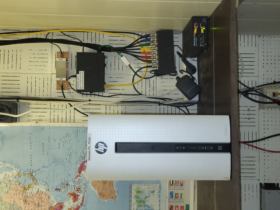
An overview of the complete skimmer setup.
Left the PC with all the software and its a Win11 with Intel I7 CPU. The software consists of CW skimmer server, RTTY skimmer server and Aggregator for the Reverse beacon connection.
Right top the N2WQ HF filter. Below the HD-SDR. At bottom the 7 way HF combiner.
The SDR
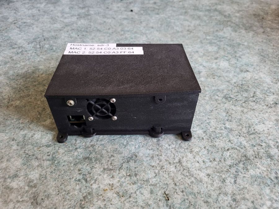
The SDR is build around a QMTECH ZYNQ7000 XC7Z020. Pavel Demin has build a HF frontend and wrote the needed software. The SDR has 2 * 8 HPSDR compatible receivers and is connected via LAN.
More info on the SDR via this link.
N2WQ HF filter
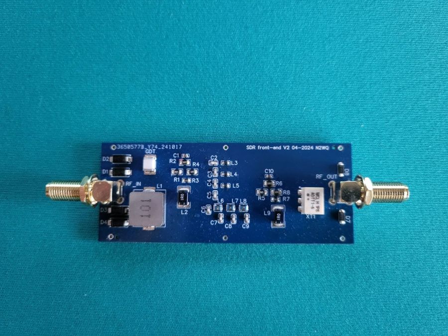
To protect the SDR from strong signals at the lower HF bands, N2WQ has developed a high pass filter to protect the higer frequenties for overload.
More info via this link.
3 dB splitter
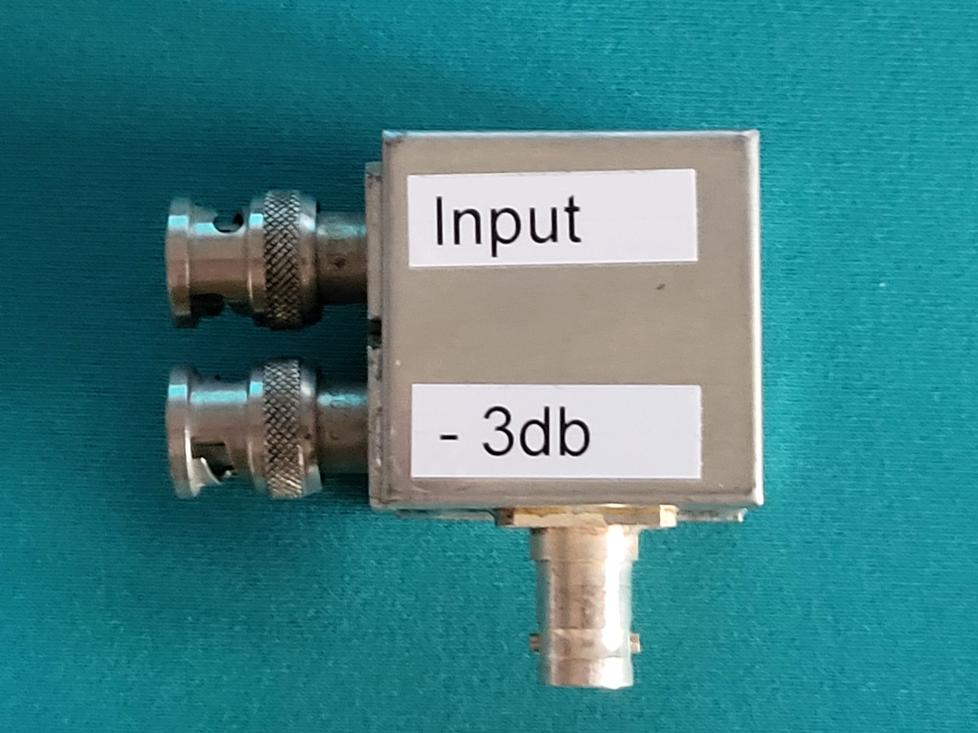
Via the RX out and RX in at the black plane of the K3 we can reroute the HF signal from the main antenna to 2 times a -3db signal. One is used to feed the K3 receiver and the second the SDR.
The splitter is build around a minicircuit splitter named ADP-2-1.
HF combiner
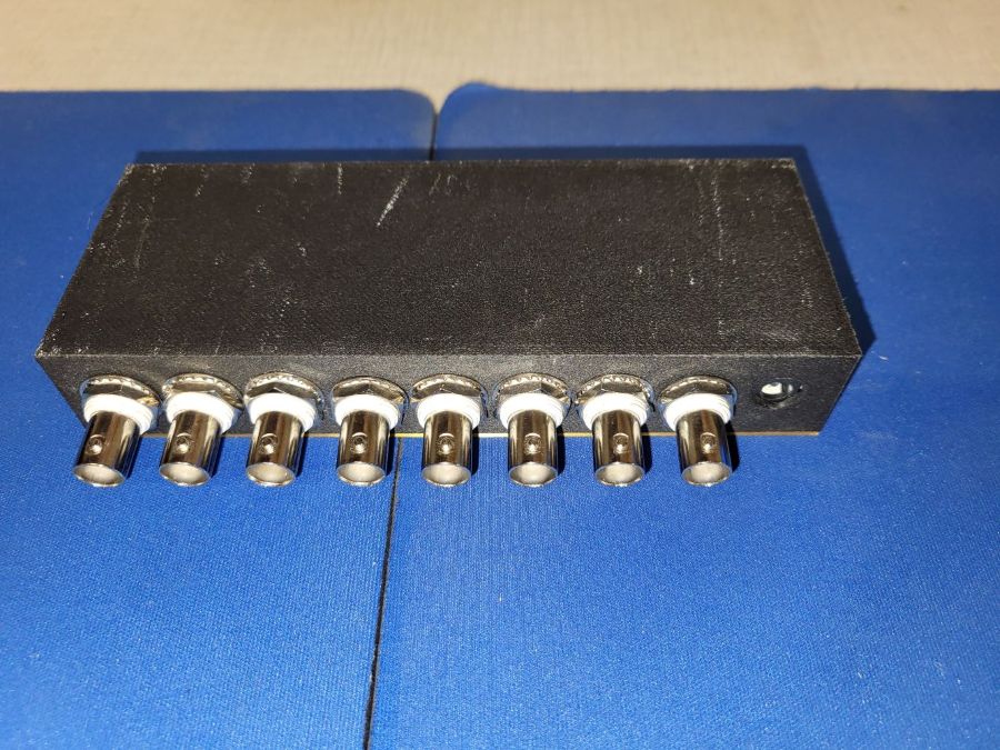
Via an active combiner we put all signals together to feed the sdr.
A PDF with the schematic is here.
Keep in mind, there are filters in front of the K3. Those filters reject signals the unwanted band.
© Copyright 1996 - 2026 PI4CC All rights reserved.